Inline deployment with an isolated virtual LAN and virtual applications
In this use case, the Exinda Virtual Appliance is set up for an inlineIn network terminology, an inline device receives packets and forwards them to their intended destination. Routers, firewalls and switches are examples of inline devices. The inline designation also alerts you the device is critical to network function. If the device goes down, network traffic is affected. mode deployment with an isolated virtual LANLocal area network and virtual applications. There are primarily two scenarios for inline deployment of the virtual appliance:
- The LAN side users and applications connect to the Exinda Virtual Appliance through a physical NIC interface.
- The applications are virtualized and isolated on the same host as the Exinda on the LAN side interface of the Exinda Virtual Appliance.
This use case discusses the second scenario.
NOTE
This scenario is only possible using VMware vSphere (v5.5 and v6.0) and Citrix XenServer (v6.2 and v6.5) hosts. Microsoft Hyper-V does not support inline deployments.
Scenario

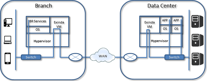
Scenario details
- Branch users access virtualized local services (such as print, DHCPDynamic Host Configuration Protocol, and Active Directory).
- One physical NIC interface is configured to the WANWide Area Network side link.
- Two virtual switches are bridged together in the virtual Exinda Virtual Appliance. The first switch is on the LAN side; the second one is for the WAN side. This results in isolating the applications behind the Exinda Virtual Appliance.
- Users connecting from the branch office to the Data Center applications are in line through the Exinda virtual machine(s) on both ends of the connections and through a single external NIC interface to the WAN.
- The Exinda appliance provides Diagnostics, Shaping, and Acceleration for all traffic in this configuration.
Use-case
This configuration will be in either a branch office with virtual infrastructure, or in the data center where the applications are running on the host VM and local users accessing the WAN leverage the Exinda for Diagnostics, Shaping, and Acceleration.

Use-case for Inline deployment with an isolated virtual LAN and virtual applications
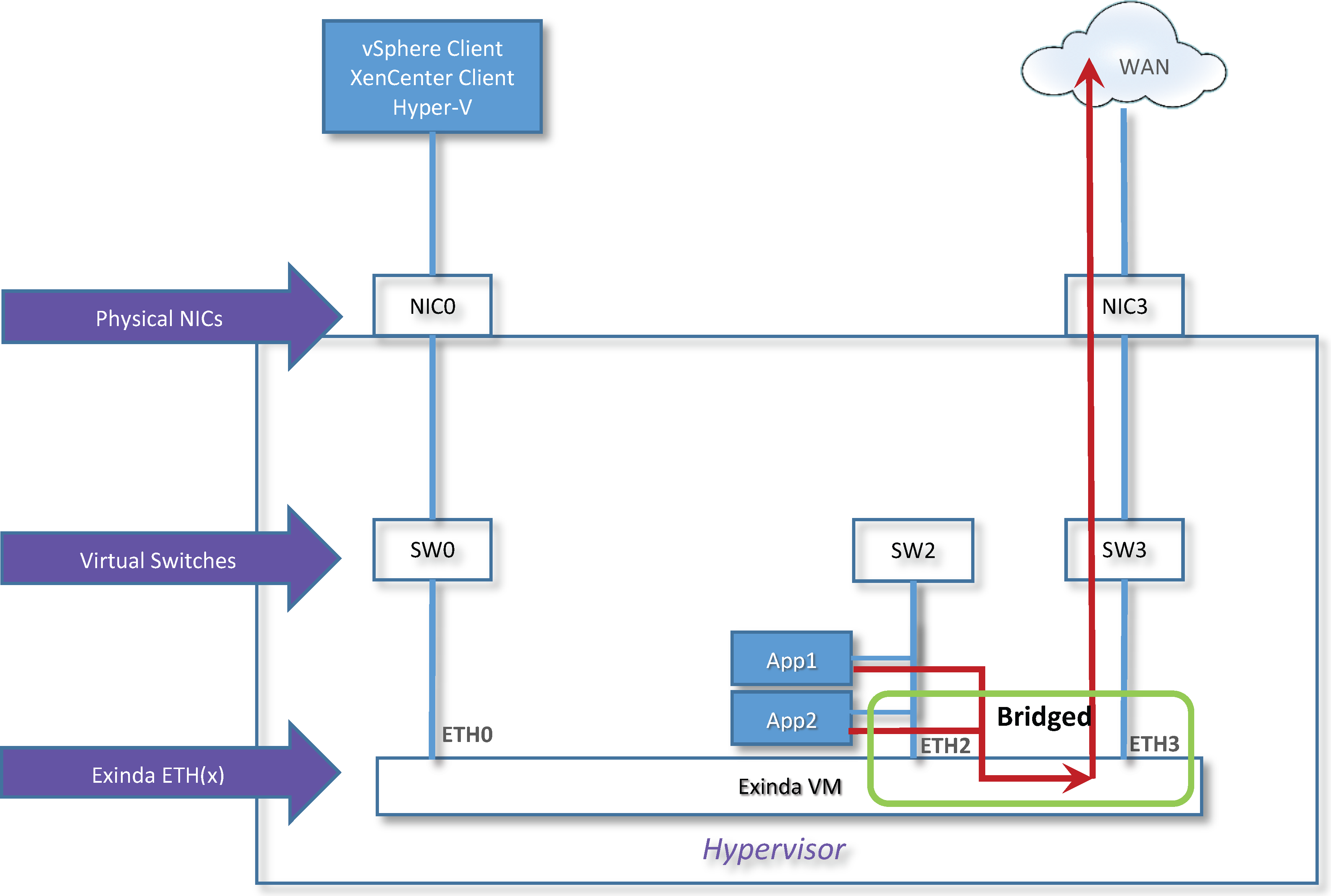
- In the diagram above, a virtual LAN is isolated and sits behind the Exinda Virtual Appliance all running on the same host hypervisor.
- The host has two NICs; NIC 0 is dedicated for management of the system and NIC 1 is idle or used for other purposes.
- All virtual application workloads are configured in the hypervisor to SW2.
- SW2 is configured to map to Exinda Virtual Appliance ETH2
- ETH2 is configured as part of a bridged connection defined as BR2.
- BR2 bridges NIC 2 and NIC 3 together in the Exinda virtual appliance. The data path for any application connected to the SW2 virtual switch goes through the Exinda Virtual Appliance in inline mode through the ETH2/ETH3 bridged configuration and out the NIC3 interface to the WAN.
- OPTIONAL: If this is a branch office with local users, configure local users to connect through the NIC2 physical interface and SW2/ETH2 Exinda Virtual Appliance interface and out to the WAN. This require mapping a third NIC interface.