Circuits
Circuits define physical connections to the WANWide Area Network/Internet. For appliances with more than one bridge configured, you can bind each bridge to a separate circuit or you can treat all bridges as one combined circuit. Typically, when the appliance is placed in line, one circuit would be created for each physical link.
When defining circuits, ensure each bridge is bound to a circuit; otherwise network traffic on any bridge that is not bound to a circuit, will not be affected by policy and will be monitored in a catch-all circuit.
NOTE
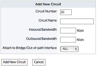
- For version 7.0.2 and earlier: A circuit can only be bound to one bridge, or all bridges (but not greater than 1 bridge and less than all bridges) or one WCCP interface.
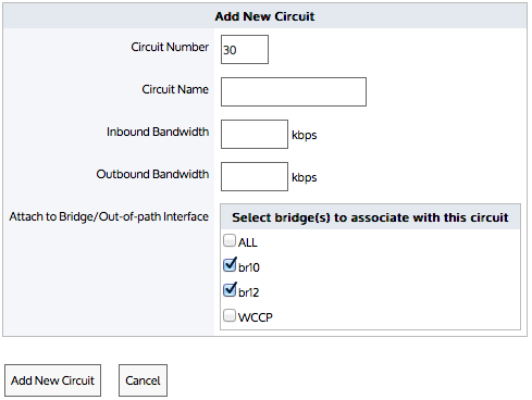
- For version 7.0.2 Update 1 and later: A circuit can be bound to any number of bridges or one WCCP interface.

Circuit form for versions 7.0.2 and earlier

Circuit form for versions 7.0.2 Update 1 and later
Circuits are part of the policy tree. To learn how circuits, virtual circuits, and policies work together, see Policy Tree.
Can a bridge be bound to more than one circuit?
A bridge can be assigned to more than one circuit. Once a type of traffic matches a virtual circuitlogical definitions that partition a a physical network circuit and used to determine what traffic passes through it and how much and policy, it will not be processed by later circuits, virtual circuits, and policies. If the type of traffic does not match any policy in the first circuit, then it will attempt to match the policy in the second circuit.
For example, consider where circuits, virtual circuit, and policy are defined as:
- Circuit A = br10
- Virtual Circuit
- Policy for P2P
- Circuit B = All bridges
- Virtual Circuit
- Policy for Mail
In this case, br10 is assigned to both circuit A & B. However, br10 is bound to circuit A first.
- If the traffic is P2P, then that traffic type will be processed by Circuit A and will not be processed by Circuit B.
- If the traffic is mail, then that traffic type will not match Circuit A. It will attempt to match policy in Circuit B. In this case, it will match the policy for mail.
- If the traffic is not P2P or mail, then that traffic type will not match Circuit A or Circuit B and therefore will fall into an auto-catch-all circuit, auto-catch-all virtual circuit, and auto-catch-all policy.
 Creating a circuit in the Exinda Web UI
Use the following instructions to create a new circuit.
- Go to Configuration > Traffic Policies > Optimizer > Optimizer, then click the Create New Circuit... link at the bottom of the page or edit an existing circuit.
- In the Circuit Number field, type the ranking order of the circuit, relative to other circuits.
- Enter a name for the circuit.
- Identify the available Inbound and Outbound bandwidth of the circuit.
- If the circuit is symmetric, the inbound and outbound bandwidth values should be the same.
- If the circuit is asymmetric, the inbound and outbound bandwidth values will be different.
- Specify the bridge or out-of-path interface to which to bind the circuit. All bridges, individual bridge names, policy-based routing interfaces, and WCCP interfaces are available.
- Click Add New Circuit.
 Creating a circuit in the EMC
Circuits define physical connections to the WAN or the Internet. A circuit defines the inbound and outbound bandwidth and the named circuit type.
On an Exinda Appliance, a circuit specifies the named bridge (or bridges) to which it is bound. In the Exinda Management Center, the binding to bridges is through a designated Circuit Type. Circuit Types represent the intended use of a circuit. So you can configure a circuit for multiple appliances without requiring the bridges on the appliances to have the same name. This is favorable where the number of bridges or names of bridges or the cabling of the bridges is not consistent across the appliances.
If multiple bridges on an appliance are mapped to the same Circuit Type, then all those bridges will be bound to the single circuit in the Policy Tree that is configured with that Circuit Type. To learn how Circuit Types are used to determine which circuits are sent to the appliances, read Circuit Types.
Circuits can be created in the Configuration Library directly and then later assigned to an Optimizer Policy Tree, Circuits can also be created in an Optimizer Policy Tree, from where the configuration is saved to the Configuration Library so that it can be used elsewhere. The circuits within a tenant must have unique names. When a circuit is modified, all uses of it are modified.
Circuits are part of the Optimizer Policy Tree. To learn how circuits, Virtual Circuits, policy sets, and policy rules work together, see Policy Tree.
 Where do I find circuits?
Circuit librarythe Exinda repository for network objects and their definitions items can be found in Library > Circuits. Also, the circuits that are applied to appliances can also be found in the policy trees for each appliance group. Go to the (desired appliance group) > Optimizer Policy Tree.
 To create a circuit in the Configuration Library
- Go to Library > Circuits.
- Click Create new circuit in the library ...
- In the Name section, key-in the name of the circuit. The name must be unique in the tenant.
- In the Bandwidth section, key-in the Inbound Bandwidth and the Outbound Bandwidth. The bandwidths can be specified in kbps, Mbps, or Gbps.
- In the Bind to Circuit Type section, select the Circuit Type.
NOTE
The circuit type represents the purpose of the circuit; it is a user created object. If the desired circuit type does not exist, you can click Create new circuit type in the library to create it. For more information refer to Circuit types in the EMC.
- Click Create . The circuit appears in the library list.
 To create a new circuit directly in the Policy Tree
- Go to the (desired appliance group) > Optimizer Policy Tree.
- Click Create new circuit.
- In the Name section, key-in the name of the circuit. The name must be unique in the tenant.
- In the Bandwidth section, key-in the Inbound Bandwidth and the Outbound Bandwidth. The bandwidths can be specified in kbps, Mbps, or Gbps.
- In the Bind to Circuit Type section, select the Circuit Type.
NOTE
The circuit type represents the purpose of the circuit; it is a user created object. If the desired circuit type does not exist, you can click Create new circuit type in the library to create it. For more information refer to Circuit types in the EMC.
- Click Save. The circuit is added to the Policy Tree and is also saved to the configuration library.
 To add a circuit to a Policy Tree
- Go to the (desired appliance group) > Optimizer Policy Tree.
- Click Add circuit from library.
- Select the desired circuit from the drop-down list.