Advanced features
Here you can find the advanced features of the Exinda SD-WANSoftware-Defined Wide Area Network.
By default, the LANLocal area network interface of the Exinda SD-WANWide Area Network is assigned the IPInternet protocol address 192.168.254.99. This is the IP address through which the Exinda SD-WAN Management Interface is accessed.
It is possible to change the IP address of the Exinda SD-WAN LAN interface. This should be done with extreme care, as changing this affects the manner in which the Exinda SD-WAN Management Interface is accessed. In particular, it is important to remember the IP address that is assigned to the Exinda SD-WAN LAN. It is not possible to access the Exinda SD-WAN Management Interface without this information.
To set the Exinda SD-WAN LAN IP address, click the Home tab of the Exinda SD-WAN Management Interface. In the LAN configuration table, in the Interface column, click LAN. A prompt appears requesting for an IP address. If the value is changed for this IP address, it is imperative that the new value be remembered. The network mask for the Exinda SD-WAN LAN can also be set under Mask. By default, the network mask is set to 255.255.255.0.
The DHCPDynamic Host Configuration Protocol server on the Exinda SD-WAN can be enabled or disabled via the radio buttons on the Home tab in the LAN configuration table. The “starting IP address” for the DHCP server can also be configured here. When the DHCP server inside the Exinda SD-WAN is enabled, it starts assigning dynamic IP addresses starting from the configured address. This may be useful in some cases to avoid conflicts with manually assigned static IP addresses. The default starting IP address is 192.168.254.100. An ending IP address can also be specified. The default ending IP address is 192.168.254.254.
The DHCP server is enabled by default. It is automatically disabled when the Pass Through mode is enabled on any of the WAN ports.
The specified IP address range for DHCP is also the range of local IP addresses that can be reached by VPNVirtual Private Network clients that are terminated on the Exinda SD-WAN.
The DHCP lease time and maximum number of leases can be set from the “DHCP Server Additional Settings” section in the Advanced tab. The gateway IP and WINS Server IP may also be set there. The name of the server IP for internal domains may be specified as well.
The Exinda SD-WAN is able to terminate VPN connections by using the PPTPPoint-to-Point Tunneling Protocol protocol. By default, this feature is disabled.
To configure this feature, select the Advanced tab within the Exinda SD-WAN Management Interface and click on the entry for PPTP in the table (the default entry is Disabled). A pop-up window appears, which allows this feature to be configured. To enable the feature, select Enable and enter a name and password pair, and click Apply.
After the feature has been enabled, PPTP clients may access the LAN by using the same address range as DHCP with the specified name and password.
By default, the Exinda SD-WAN is configured to support UPnPUniversal Plug and Play which enables auto-configuration of IP addressing features for certain applications.
Normally, support for UPnP should be disabled when running the Exinda SD-WAN in the Pass Through mode since this functionality would already be provided by a device in the legacy network.
Inbound port forwarding allows external computers on the internet to access devices in the local network through the same IP address. Normally this feature is used with static IP address assignment, but it can be used with any of the IP address configuration modes for the Exinda SD-WAN WAN ports. Inbound port forwarding is not recommended for the Pass Through mode of operation on WAN interface 1, since this function, if required, would already be handled by the legacy network that was kept intact without any changes during the installation.
By default, all inbound Internet traffic is blocked, except for ICMPInternet Control Message Protocol traffic. Selected inbound internet traffic can be allowed or blocked by configuration of one or more forwarding rules. To configure a rule for forwarding inbound Internet traffic, select the Firewall tab, and click Add Firewall Rule. Select Inbound as a Direction.
In order to configure a rule for forwarding inbound Internet traffic, an Interface must also be specified on the pop-up menu. You can specify ALL WAN which means that traffic from all WAN interfaces, wired or cellular is the target of the rule. Alternatively, a forwarding rule for a single WAN interface can be specified in the drop-down menu. In order for cellular WAN interfaces to become available, the corresponding cellular WAN interface should be configured first. In addition, if any remote LAN connections have been configured (with the optional VLL feature), they also appear in the menu as possible targets of the forwarding rule.
Traffic from a specific protocol or from all protocols can be specified as the target of the forwarding rule by selecting under Protocol/Action. TCPTransmission Control Protocol, UDPUser Datagram Protocol, ICMP, IPSecInternet Protocol Security, and PPTP are available, as is Any which is interpreted as all protocols. A specific protocol other than the above can also be specified by selecting Other and entering the corresponding protocol number.
Adding an inbound forwarding rule causes the targeted traffic to be forwarded to the Local IP address designated in the pop-up menu, unless the Discard option is selected in which case the targeted traffic is discarded.
Specifying a WAN port number causes all traffic destined to the specified port to be forwarded to the specified Local IP address. More generally, a range of WAN ports can also be specified by designating a second WAN port, which is the end of the port range. It is delivered to the same destination port unless a LAN port is specified, in which case it is delivered to the specified LAN port.
A Global IP address may also be optionally specified, which signifies that only that traffic which is destined to the specified Global IP address should be forwarded to the specified Local IP address.
A text string can also be entered in Notes, to provide a mechanism for the operator to remember the reason or context of the forwarding rule.
After specifying all desired conditions in a forwarding rule for inbound traffic, click Add to load the forwarding rule into the Exinda SD-WAN. Multiple forwarding rules can be added to provide more flexible forwarding of traffic. If a forwarding rule that was added previously needs to be deleted, click Delete next to the listed forwarding rule. If a forwarding rule needs to be edited, the rule can first be deleted and the modified rule can then be entered as before. The Exinda SD-WAN processes arriving traffic by sequential application of the specified forwarding rules. This means if there are conflicts in the forwarding rules, the forwarding rule nearest the top of the list takes precedence. By default, the list of forwarding rules is such that rules entered earlier is lower in the list, so the most recently added rule always take precedence.
Here is an example scenario for a user accessing his desktop remotely:

Example scenario for a user accessing his desktop remotely
Outbound port blocking allows a network operator to block all outgoing traffic from a specified source port, protocol, and optionally a specified source IP address or subnet.
By default, all outbound internet traffic is allowed. To configure a rule for blocking outbound Internet traffic, click the Firewall tab to display the menu and click Add Firewall Rule. Select Outbound as a Direction. Use the menu under Protocol/Action to select which protocol should be denied outbound access.
Alternatively, you can specify an arbitrary protocol by selecting Other and entering the corresponding protocol number. You can also select Deny Any to deny all outbound traffic based on protocol. Finally, you can select the No NATNetwork Address Translation option if you wish to disable the Network Address Translation (NAT) function on the specified outbound traffic. By default, NAT is applied to all outgoing traffic, meaning that the source IP address of egress packets that originate on the Exinda SD-WAN LAN is replaced with the IP address of the corresponding WAN interface, and selecting the No NAT option disables the NAT function for the targeted traffic.
Optionally, a Source Port index for the targeted traffic can be specified. Thus, only packets with a Source Port value matching the entered value is targeted. Also optionally, a source IP address can be specified so that only traffic with a source IP address matching the designated address is targeted. Generally, an IP subnet can also be specified in CIDRClassless Inter-Domain Routing notation, for example, 192.168.1.0/24. In this case, traffic originating from the specified subnet is targeted. The targeted traffic by definition satisfies all the matching conditions, so that effectively the conditions are logically concatenated to specify the targeted traffic.
A text string can also be entered in Notes, to provide a mechanism for the operator to remember the reason or context of the outbound rule.
Multiple outbound blocking rules can be added to provide more flexible blocking of traffic. If a traffic blocking rule that was added previously needs to be deleted, click Delete next to the listed blocking rule. If a blocking rule needs to be edited, the rule can first be deleted and the modified rule can then be entered as before. The Exinda SD-WAN processes outgoing traffic by sequential application of the outbound rules specified. This means if there are conflicts in the outbound rules, the outbound rule nearest the top of the list takes precedence. By default, the list of outbound rules is such that rules entered earlier is lower in the list, so the most recently added rule always takes precedence.
Normally outbound blocking rules should not be specified when the Exinda SD-WAN is configured in Pass Through mode since such blocking would already be done by the legacy network.
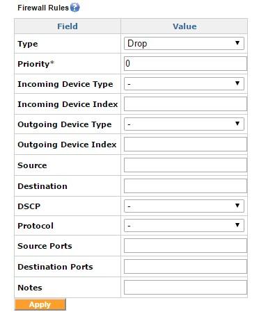
The Firewall Rules configuration screen
The advanced firewall rules allow characterizing traffic based on the Incoming Device Type and the Outgoing Device Type, or both. The “Type” field is the action that the rule takes on the traffic that is matched. The type can be either ACCEPT, DROP or REJECT. ACCEPT takes the matched traffic, DROP drops the traffic and REJECT would send an ICMP unreachable packet to the sender and then DROP the packet.
The traffic can be filtered based on the Source IP, destination IP, source ports or destination ports. An IP subnet also can be specified with a CIDR notation, e.g. 192.168.1.0/24.
Multiple firewall rules can be added to achieve a combination by means of priority. The priority is in ascending order, so the rule with a lower priority is processed first. So to accept a particular IP address and drop all other traffic, we have the ACCEPT rule with a lower priority and the DROP rule with a higher priority.
Support for a DMZDemilitarized Zone (demilitarized zone) can be enabled through the Firewall tab within the Exinda SD-WAN Management Interface.
The DMZ feature of the Exinda SD-WAN allows the user to specify the IP address of a local computer that has been designated as the DMZ. The specified IP address is called the "DMZ IP address". When the Exinda SD-WAN receives a packet from the internet over any of the WAN ports then the Exinda SD-WAN forwards the packet to the specified DMZ address if none of the port forwarding rules apply to the given packet.
If no port forwarding rules are specified and a DMZ IP address is specified, then all packets received on a WAN port is forwarded to the local computer with the specified DMZ IP address. It should be noted that if one or more port forwarding rules are specified that they take precedence over the forwarding of traffic to a DMZ, if the DMZ feature is enabled. Moreover, it should be noted that any port forwarding that occurs as a result of the UPnP feature being enabled takes precedence over any port forwarding rules.
Setting up a DMZ is useful if there are several computers in the local network, but only one of them (that has been designated as the DMZ) is desired to be directly accessible via the Internet. Normally, support for DMZ should be disabled when running the Exinda SD-WAN in the Pass Through mode since a DMZ would already be implemented in the legacy network.
The DMZ feature can be configured by clicking on the status Enabled or Disabled for DMZ in the configuration table and selecting the appropriate radio button. If Enable is selected, then the IP address for the DMZ must be specified. When you click Apply, the DMZ feature is configured accordingly.
The Exinda SD-WAN supports inbound load balancing and inbound link fail-over via Dynamic DNSDomain Name Server (DDNSDynamic DNS). This feature allows management of inbound traffic (traffic which is originally initiated from the Internet). This feature is configured via the Advanced tab. It is disabled by default and three modes are supported currently through the Dynamic DNS service at afraid.org, dyndns.org, and changeip.com. To properly configure this feature, a service account should first be set up with afraid.org, dyndns.org, or changeip.com. Details of the service are available from these service providers. Once the service account has been set up the corresponding mode can be selected by clicking on the status entry (“Disabled” or “Enabled”) for “Dynamic DNS” in the configuration table. The various options is displayed, and the Exinda SD-WAN Management Interface then prompts for a Username, Password, and Hostname, which should be provided by the Dynamic DNS provider. By clicking Apply, the Dynamic DNS feature is configured accordingly.
For afraid.org's round-robin DDNS to work correctly, it requires unlinking of entries for the same domain (one entry for each Exinda SD-WAN WAN connection is required). For more information, see the afraid.org FAQ at http://freedns.afraid.org/.
Support for dynamic DNS on multiple interfaces is also available.

Multiple DYNDNS Setup screen
Weights may be set per interface for load balancing. These weights adjust the proportion of traffic that is handled by each WAN interface.
To configure these, click the Advanced tab and then click Add next to Load Balancing Weights.
For setting the weights per interface, it is recommended that you use the rounded value of the kbit/s rate of the respective WAN interfaces.
The settings for connectivity check may be adjusted on the Advanced tab of the Exinda SD-WAN Management Interface. These settings determine how the Exinda SD-WAN discovers and monitors the connectivity of the individual WAN interfaces.
The Exinda SD-WAN attempts to reach external servers to determine if a WAN interface is successfully connected. The connectivity check proceeds in three phases:
- Resolving connectivity check addresses
- Pinging connectivity check addresses
- Simultaneously pinging and attempting HTTP connections to connectivity check addresses
The maximum duration (in seconds) of each phase may be adjusted by clicking Settings in the Index column of the Connectivity Check Settings configuration table. If desired, to immediately check HTTP in addition to ICMP, the time for the ping phase may be reduced to zero. Be aware, though, of the bandwidth overhead of retrieving HTTP responses on very limited lines.
The Exinda SD-WAN internally manages a list of active server IPs that is used for these checks, which are automatically updated as long as the Exinda SD-WAN maintains a connection to the internet. Additional servers may be added manually by clicking Add next to Additional Remote Servers for Connectivity Check on the Advanced tab and entering the server’s IP address. These servers should be responsive to ICMP or HTTP requests, or both, and be available with high reliability.
A list of all dynamic IP addresses leased out by the Exinda SD-WAN DHCP server can be viewed on the Status tab. The MACMedia Access Control address, IP address, and possibly the machine name are listed for each IP address lease.
A log of Exinda SD-WAN system events appears in the Status tab. The IP address of a Remote Syslog Server can be specified which is to be the recipient of log messages generated by the Exinda SD-WAN. After the IP address of the Remote Syslog Server has been specified, click Apply to configure this feature.

The Domain Name Blocking / DNS Redirection Menu
Domain name blocking / DNS redirection is used to block a site or used to redirect to a particular IP for a site. For the DNS redirection to work, the Exinda SD-WAN device should be configured the same as the DNS server in the local network.
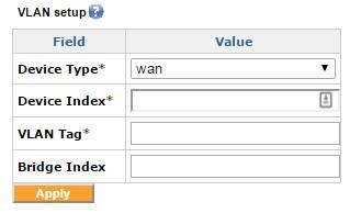
The VLAN Setup menu
The VLAN setup can be used for creating 802.11q format frames with a particular tag. The "Device Type" would be WAN, LAN, or Cellular, followed by the "Device Index" which would be the index number. For WAN 1, you would enter '1' here. The "VLAN Tag" field contains the tag number, and "Bridge Index" contains the bridge index.

The Netflow Settings menu
The netflow settings are used to configure sending netflow data to a netflow server on the local area network of the Exinda device. The required parameters are the Netflow Server IP and the Netflow Server Port. The Netflow Version supports versions 1, 5, and 9.
Manual routes are used in scenarios where you have multiple subnets on the LAN segment, or you want to specify certain subnet traffic to use a specific Remote LAN, or WAN, link. This feature can be configured by going to the Advanced tab on the Exinda SD-WAN Management Interface and clicking Add next to the Manual Network Routes section:
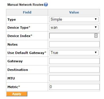
Manual Network Routes, Simple
This generates a pop-up window where the information specifying a manual route rule can be entered. The Type field specifies Simple Route or Advanced Route. Device Type identifies the interface/tunnel type for the traffic we are setting the route for. As an example, WAN or LAN subnets or VLL if the traffic is destined for a VLL tunnel. The Destination field specifies the destination IP address subnet to which the packets are routed to. This can be accomplished either through a device route or through a VLL route, based on the option chosen previously.
Choosing the Advanced Route as the Type exposes additional configuration options to identify the traffic including Source IP/Subnet, DSCPDifferentiated Services Code Point, Protocol, Source Ports, and Destination Ports. You can also modify the Priority and the Maximum Transmission Unit (MTUMaximum Transmission Unit) size of the traffic.
The failover mode is used to configure the failover action in case of primary interface failure. It has 2 modes: “sticky mode” and “available mode”. In case of a primary interface failure, the sticky mode transfers the traffic on to the secondary interface, and when the primary line comes back up, transfers the traffic back to the primary interface. With the “available mode”, after the primary interface recovers, the traffic that failed- over earlier continues to use the failover interface. The newer sessions is routed over the primary interface as usual.
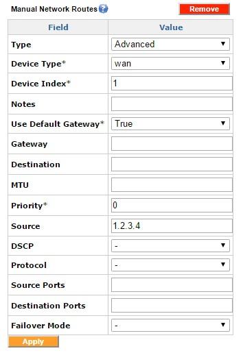
Manual Network Routes, Advanced
An “interface group” is an abstraction of a set of real interfaces that the user can manage with finer control. The user can define what interfaces (WAN, Cellular, VLL) are to be associated with a particular interface group, what percentage of each interface is to be used and if the group requires failover interfaces. The user can also define what type of traffic would traverse this bundled virtual interface.
Components of interface groups
Interface groups
This block gives the user the functionality to create a group which could then have filters and the outgoing interfaces associated with it.
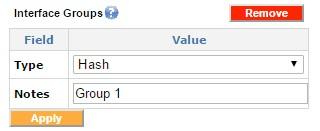
Adding interface groups
Interface group interfaces
Once an interface group is created, the group's specific interfaces can be configured and added to the interface group. For instance the user can add WAN 1 and Cellular WAN 2 to a particular interface group.

Interface group interfaces
In this example only WAN1 and Cellular WAN2 is included in this group.
Interface group filter
The interface group filter is used to filter the desired traffic types on a particular Interface Group.
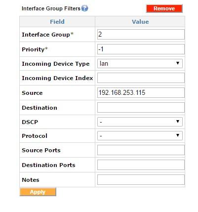
Adding interface group filters
This sample filter directs all traffic from 192.168.253.115 onto Interface Group 2.

Interface Groups
The blank Device Index in this example indicates that all device type indexes should be selected.
The distribution of traffic within this interface group can be customized by using Weights. The “weight” indicates the proportion of traffic desired for a particular interface. A weight of 0.0 for all interfaces selected indicates an equalized distribution of the traffic. This would match all the incoming traffic on the LAN. These weights can be customized to load balance by changing the weights as desired.
Enable Capture All with group interfaces
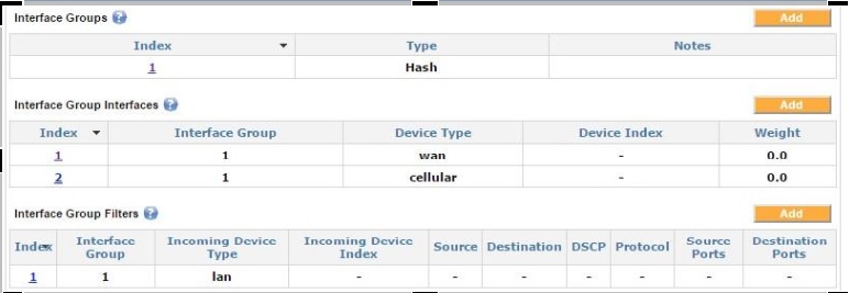
Enabling Capture All with interface groups
In this example, the weight of 1.0 for the VLL tunnel ensures all the traffic goes over the VLL interface. The other interfaces have weights of 0.0, which makes them a failover interface and only activate them in case the primary interface (in this example, the VLL interface) goes down.
Load balancing by using the interface groups

Load balancing with interface groups
Load balancing weights can be defined for each interface contained in the interface group interfaces. These weights indicate the proportion of traffic desired for the given interface.
In this example, the weights are set to 0.7 for WAN1 and 0.3 for WAN2, which results in 70% of the traffic being directed to WAN1 and 30% of the traffic being directed to WAN2.
Random group

Random interface group
In this example, the traffic matching the filter is randomly distributed across all interfaces that are included in the interface group interfaces for that group. Note that since the Device Index is left blank, then all WAN interfaces are included in this group. This load-balancing algorithm is essentially a round-robin algorithm.

VLAN tagging
The VLAN tags can be set for both WAN and LAN interfaces. The Device Type can be WAN or LAN, the Device Index here is the index number. The VLAN Tag field contains the tag number.

A Bridge alias
The Bridge alias is used to add a subnet alias to the LAN interface. This feature can be useful if there is more than one subnet in the local network.
The QoSQuality of Service feature can be configured through the Advanced tab on the Exinda SD-WAN Management Interface. This feature is used to guarantee a certain bandwidth for an application or to prioritize certain traffic, such as Citrix or SIP.
Quality of Service shapers
In order to use the QoS feature, a user must first create the WAN Shaper rule (Quality of Service Shaper) on the Advanced tab. A rate that is 85% of the rate provided by the ISPIntenet service provider should be used as the shaper rule both for uplink (egress) and downlink (ingress).

Quality of Service shaper example
In this example, the ISP uplink rate is 705 kbps, so the egress shaper for WAN1 is set to 85% of the available bandwidth, or 600 Kbps.
Quality of Service reservations
After creating the shaper rule for both ingress and egress, the application traffic reservation and prioritization can be created using Quality of Service Reservations. The following example illustrates how to reserve 200 Kbps uplink for IPSec traffic:

Quality of Service reservation example
For prioritizing real time traffic, the Priority field can be changed from Normal Priority to High Priority. Advanced application specific QoS can be achieved with Exinda Network Orchestrator. For more information, see www.gfi.com/exinda.
Prioritization of VLL traffic (example)
- On the Advanced tab, add a new QoS reservation rule with the destination port as 9899 for the UDP protocol .
- Create another rule using port 9899 in case your remote LAN has both client and server configured on the same GFI device:

Example of prioritization of VLL traffic
The Exinda SD-WAN can be configured to peer/mate with another Exinda SD-WAN device that has a server license to create a data communication tunnel between the pair of Exinda SD-WAN units. By virtue of combining the capacity of multiple resources, the capacity of the tunnel created can be close to the sum of the capacities of the individual resources. Moreover, the reliability of the communication tunnel is increased since the communication tunnel remains operational as long as there is at least one active communication path between the Exinda SD-WAN devices.
It is also possible for each Exinda SD-WAN to peer with multiple Exinda SD-WAN devices. A bi-directional tunnel can be set up between each pair of Exinda SD-WAN devices as long as one Exinda SD-WAN has the server license activated. For each bidirectional tunnel, one Exinda SD-WAN device is designated as a “server” and the other is designated as a “client”. For example, one Exinda SD-WAN device might act as a server for several other Exinda SD-WAN devices, each of which acts as a client.
A tunnel can be configured in two possible modes, “default” and “proxy”. For each end of the tunnel, there is an associated LAN address. In the default mode, traffic that appears at one Exinda SD-WAN that matches the associated LAN address of the remote Exinda SD-WAN is forwarded to the remote Exinda SD-WAN through the tunnel. In the proxy mode, all traffic that appears at the Exinda SD-WAN on the client side that does not match the local LAN address is sent to the remote Exinda SD-WAN device over the tunnel. Also, in proxy mode, traffic appearing at the Exinda SD-WAN on the server side that matches the LAN address of the Exinda SD-WAN on the client side is forwarded to the Exinda SD-WAN device on the client side over the tunnel. LAN addresses are specified by an IP address and associated network mask.
The VLL feature is configured on the Home tab of the Exinda SD-WAN Management Interface, in the Remote LAN table. It looks similar to the following:

Remote LAN example
To create a tunnel, two Exinda SD-WAN devices are required. A tunnel is configured by creating an instance of a server connection at one Exinda SD-WAN and creating a matching instance of a client connection at the other Exinda SD-WAN. For security purposes, each bi-directional tunnel has an associated connection name and password, which must be specified identically at each end of the tunnel when the tunnel is configured.
By default, packets that are sent over the tunnel are encapsulated in UDP packets in order to provide robustness against certain types of packet filtering that may be commonly present in ISP access networks.
To create an instance of a server connection or a client connection at a Exinda SD-WAN device:
- Go to the Home tab of the Exinda SD-WAN Management Interface for that Exinda SD-WAN device.
- Click Add Remote LAN at the top of the Remote LAN table.
- Set the Connection Mode as Client or Server in the menu at the top of the pop-up.
To configure the device in the Server mode:
- Select Server for the Connection Mode.
- Enter a text string for the Connection Name field, and an associated password in the Password field. To provide security, these fields must exactly match the corresponding fields for the associated connection at the other Exinda SD-WAN device in order for the tunnel to become operational.
- Specify the network address of the LAN associated with the remote Exinda SD-WAN device in the Remote LAN Network and the Remote LAN Netmask fields.
- After the parameters for the connection are entered, click Add to add the corresponding connection.
After a connection is added, the parameters can be edited by clicking on the corresponding entry in the Remote LAN table, modifying the entries in the pop-up menu, and clicking Edit. You can also remove a connection by deleting it.
To configure the device in the Client mode:
- Select Client for the Connection Mode.
- Specify which WAN ports on the Exinda SD-WAN are used for the tunnel by selecting or clearing each listed interface as appropriate, or selecting ALL to use all available interfaces for the tunnel.
- The specification of which WAN ports is used on the remote side of the tunnel (that is, the server side) is done by providing a list of IP addresses (separated by commas) of these WAN ports in the Remote IP/Name field. Alternatively, instead of a list of IP address, a DNS domain name can be entered. The domain name should resolve to the list of IP addresses associated with the server that is used for the tunnel.
- Specify the network address of the remote LAN in the Remote LAN Network and the Remote LAN Netmask fields.
- The Connection Name and Password fields should contain text strings which exactly match the associated connection entries at the remote Exinda SD-WAN.
- After the parameters for the connection are entered, click Add to add the corresponding connection.
The order in which the server and client are configured is arbitrary. Currently, the Exinda SD-WAN does not support overlapping LAN addresses on each Exinda SD-WAN; the network addresses for the Exinda SD-WAN devices at each end of the VLL tunnel must be distinct and non-overlapping. Once both the client and server devices are configured, the Status field of the Remote LAN table is appropriately updated on the Exinda SD-WAN Management Interface for each device. The entries in the Status column can be clicked on, and a pop-up menu appears that provides additional information regarding the state of the tunnel.

VLL Interfaces Sockets buffers
The VLL interface socket buffers are required in scenarios where the lines bonded by the VLL have huge difference in the latencies (for example, combining a DSLDigital Subscriber Line and a satellite line ). In these cases, fine-tuning the VLL socket buffers leads to an optimized performance.
The Exinda SD-WAN supports binding of specific outbound traffic to a specific WAN interface or VLL data tunnel (with the optional VLL feature). This is sometimes useful for some applications or users that require certain traffic to be routed over the same WAN interface or over a certain tunnel.
To configure the interface binding feature, go to the Advanced tab. To configure an interface binding rule, click Add Interface Binding Rule. This generates a pop-up window where the information specifying an interface binding rule can be specified. The rule action is specified by an Interface which can be either WIRED WAN 1, WIRED WAN 2, WIRED WAN 3, WIRED WAN 4, or possibly Cellular WAN 1 if a cellular broadband data modem is plugged into the Exinda SD-WAN. If a remote LAN connection has been defined (with the optional VLL feature), that can also be specified as an interface.
The specified traffic is preferentially routed over the WAN interface with the index that is selected for the rule, or to the corresponding remote LAN connection.
The traffic specification for the rule consists of a protocol designation, a port number, and an IP address or IP subnet. Only packets which match the corresponding protocol designation, port number, and IP address or IP subnet is affected by the rule (that is, the “and” of these three conditions). A match for the port number occurs when either the Source Port field or the Destination Port field matches with the port numbers specified. A port number specification can be a single integer, but it can also be a range. For example, 56-59 would be the range that includes 56, 57, 58, and 59. Values and ranges can also be separated by commas. For example, 56,59 corresponds to the set containing the values 56 and 59. If the Port Number field is left blank, there is no match condition applied to the Source Port or Destination Port fields, that is, all ports match.
A match for the IP address occurs when either the source IP address of the packet or the destination IP address of the packet matches the given IP address. If an IP subnet is given, a match occurs when the source IP address or the destination IP address of the packet is within the IP subnet. If the IP address / subnet field is left blank then there is no match condition applied to the IP address field, that is, all IP address / subnet values matches.
The protocol designation can be ANY, TCP, UDP, IPSEC, PPTP, or Other. The ANY choice means any protocol matches. With the Other protocol designation, the corresponding protocol number is also specified.
All of the match conditions, if any, for the port number, the IP address or subnet, and the protocol designation must be met in order to trigger the port forwarding rule. When the port forwarding rule is triggered, the traffic is routed in the manner specified, for example, WIRED WAN 1, WIRED WAN 2, WIRED WAN 3, WIRED WAN 4, Cellular WAN 1 if a cellular broadband data modem is plugged into the Exinda SD-WAN, and Remote LAN 1 if a VLL connection has been configured (with the optional VLL feature).
There are two port numbers that need special consideration for interface binding. Specifically, traffic on port 80 (HTTP) and port 443 (SSL) should be selected for interface binding only with extreme care. Nominally, traffic for these ports should be handled by the same WAN interface.
An optional Note field is provided for convenience and typically is used to document what the interface binding rule is used for (for example, for a particular application or user). Once all the information for an interface binding rule has been entered, click Add to enable the rule.
Multiple interface binding rules can be added in order to provide more flexible binding of traffic. If an interface binding rule that was added previously needs to be deleted, click Delete next to the listed binding rule. If an interface binding rule needs to be edited, the rule can first be deleted and the modified rule can then be entered as before. The Exinda SD-WAN processes outgoing traffic by sequential application of the interface binding rules specified. This means if there are conflicts in the interface binding rules, the rule nearest the top of the list takes precedence. By default, the list of rules is such that rules entered earlier is lower in the list.
VLL Cloud Relay
Each Exinda SD-WAN subscription can have up to 1 VLL connected to our Cloud Relay service. The Cloud Relay Service connects the Exinda SD-WAN device to another GFI hosted Exinda SD-WAN device, hosted on Amazon AWS. The Cloud Relay service utilizes the VLL feature explained above. To set it up, you should contact Support.