Virtual leased line
The Exinda SD-WANSoftware-Defined Wide Area Network can be configured to peer/mate with another Exinda SD-WANWide Area Network device that has a server license to create a data communication tunnel between the pair of Exinda SD-WAN units. By virtue of combining the capacity of multiple resources, the capacity of the tunnel created can be close to the sum of the capacities of the individual resources. Moreover, the reliability of the communication tunnel is increased since the communication tunnel remains operational as long as there is at least one active communication path between the Exinda SD-WAN devices.
It is also possible for each Exinda SD-WAN to peer with multiple Exinda SD-WAN devices. A bi-directional tunnel can be set up between each pair of Exinda SD-WAN devices as long as one Exinda SD-WAN has the server license activated. For each bidirectional tunnel, one Exinda SD-WAN device is designated as a “server” and the other is designated as a “client”. For example, one Exinda SD-WAN device might act as a server for several other Exinda SD-WAN devices, each of which acts as a client.
A tunnel can be configured in two possible modes, “default” and “proxy”. For each end of the tunnel, there is an associated LANLocal area network address. In the default mode, traffic that appears at one Exinda SD-WAN that matches the associated LAN address of the remote Exinda SD-WAN is forwarded to the remote Exinda SD-WAN through the tunnel. In the proxy mode, all traffic that appears at the Exinda SD-WAN on the client side that does not match the local LAN address is sent to the remote Exinda SD-WAN device over the tunnel. Also, in proxy mode, traffic appearing at the Exinda SD-WAN on the server side that matches the LAN address of the Exinda SD-WAN on the client side is forwarded to the Exinda SD-WAN device on the client side over the tunnel. LAN addresses are specified by an IPInternet protocol address and associated network mask.
The VLL feature is configured on the Home tab of the Exinda SD-WAN Management Interface, in the Remote LAN table. It looks similar to the following:
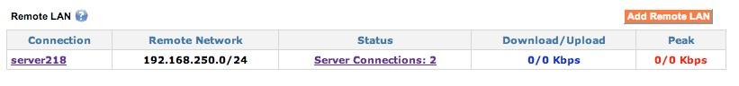
Remote LAN example
To create a tunnel, two Exinda SD-WAN devices are required. A tunnel is configured by creating an instance of a server connection at one Exinda SD-WAN and creating a matching instance of a client connection at the other Exinda SD-WAN. For security purposes, each bi-directional tunnel has an associated connection name and password, which must be specified identically at each end of the tunnel when the tunnel is configured.
By default, packets that are sent over the tunnel are encapsulated in UDPUser Datagram Protocol packets in order to provide robustness against certain types of packet filtering that may be commonly present in ISPIntenet service provider access networks.
To create an instance of a server connection or a client connection at a Exinda SD-WAN device:
- Go to the Home tab of the Exinda SD-WAN Management Interface for that Exinda SD-WAN device.
- Click Add Remote LAN at the top of the Remote LAN table.
- Set the Connection Mode as Client or Server in the menu at the top of the pop-up.
To configure the device in the Server mode:
- Select Server for the Connection Mode.
- Enter a text string for the Connection Name field, and an associated password in the Password field. To provide security, these fields must exactly match the corresponding fields for the associated connection at the other Exinda SD-WAN device in order for the tunnel to become operational.
- Specify the network address of the LAN associated with the remote Exinda SD-WAN device in the Remote LAN Network and the Remote LAN Netmask fields.
- After the parameters for the connection are entered, click Add to add the corresponding connection.
After a connection is added, the parameters can be edited by clicking on the corresponding entry in the Remote LAN table, modifying the entries in the pop-up menu, and clicking Edit. You can also remove a connection by deleting it.
To configure the device in the Client mode:
- Select Client for the Connection Mode.
- Specify which WAN ports on the Exinda SD-WAN are used for the tunnel by selecting or clearing each listed interface as appropriate, or selecting ALL to use all available interfaces for the tunnel.
- The specification of which WAN ports is used on the remote side of the tunnel (that is, the server side) is done by providing a list of IP addresses (separated by commas) of these WAN ports in the Remote IP/Name field. Alternatively, instead of a list of IP address, a DNSDomain Name Server domain name can be entered. The domain name should resolve to the list of IP addresses associated with the server that is used for the tunnel.
- Specify the network address of the remote LAN in the Remote LAN Network and the Remote LAN Netmask fields.
- The Connection Name and Password fields should contain text strings which exactly match the associated connection entries at the remote Exinda SD-WAN.
- After the parameters for the connection are entered, click Add to add the corresponding connection.
The order in which the server and client are configured is arbitrary. Currently, the Exinda SD-WAN does not support overlapping LAN addresses on each Exinda SD-WAN; the network addresses for the Exinda SD-WAN devices at each end of the VLL tunnel must be distinct and non-overlapping. Once both the client and server devices are configured, the Status field of the Remote LAN table is appropriately updated on the Exinda SD-WAN Management Interface for each device. The entries in the Status column can be clicked on, and a pop-up menu appears that provides additional information regarding the state of the tunnel.