Interface Groups
An “interface group” is an abstraction of a set of real interfaces that the user can manage with finer control. The user can define what interfaces (WANWide Area Network, Cellular, VLL) are to be associated with a particular interface group, what percentage of each interface is to be used and if the group requires failover interfaces. The user can also define what type of traffic would traverse this bundled virtual interface.
Components of interface groups
Interface groups
This block gives the user the functionality to create a group which could then have filters and the outgoing interfaces associated with it.
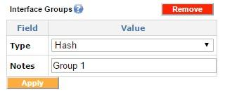
Adding interface groups
Interface group interfaces
Once an interface group is created, the group's specific interfaces can be configured and added to the interface group. For instance the user can add WAN 1 and Cellular WAN 2 to a particular interface group.
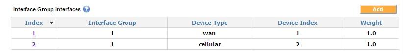
Interface group interfaces
In this example only WAN1 and Cellular WAN2 is included in this group.
Interface group filter
The interface group filter is used to filter the desired traffic types on a particular Interface Group.
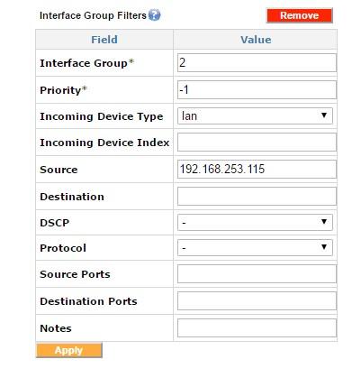
Adding interface group filters
This sample filter directs all traffic from 192.168.253.115 onto Interface Group 2.
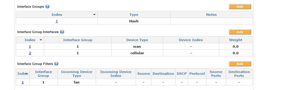
The default Interface Group with index 1 should not be modified. Any additional desired Interface Groups should be added as new Interface Groups.
Interface Groups
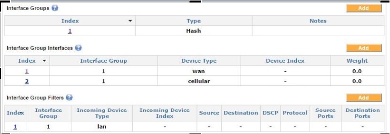
The blank Device Index in this example indicates that all device type indexes should be selected.
The distribution of traffic within this interface group can be customized by using Weights. The “weight” indicates the proportion of traffic desired for a particular interface. A weight of 0.0 for all interfaces selected indicates an equalized distribution of the traffic. This would match all the incoming traffic on the LANLocal area network. These weights can be customized to load balance by changing the weights as desired.
Enable Capture All with group interfaces
Enabling Capture All with interface groups
In this example, the weight of 1.0 for the VLL tunnel ensures all the traffic goes over the VLL interface. The other interfaces have weights of 0.0, which makes them a failover interface and only activate them in case the primary interface (in this example, the VLL interface) goes down.
Load balancing by using the interface groups
Load balancing with interface groups
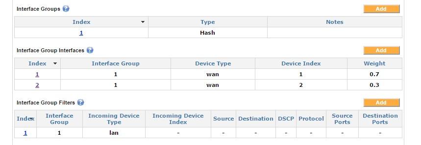
Load balancing weights can be defined for each interface contained in the interface group interfaces. These weights indicate the proportion of traffic desired for the given interface.
In this example, the weights are set to 0.7 for WAN1 and 0.3 for WAN2, which results in 70% of the traffic being directed to WAN1 and 30% of the traffic being directed to WAN2.
Random group
Random interface group
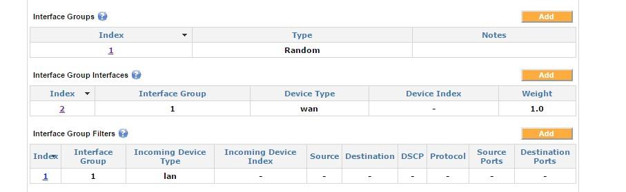
In this example, the traffic matching the filter is randomly distributed across all interfaces that are included in the interface group interfaces for that group. Note that since the Device Index is left blank, then all WAN interfaces are included in this group. This load-balancing algorithm is essentially a round-robin algorithm.
Advanced routes take precedence over the interface group filters, and therefore advanced routes can be used to create exceptions to the interface group filters.